IC LM2917 IC chip is designed specifically as a Frequency to Voltage Converter or Frequency to Voltage converter. In its use to applications Frequency to Voltage Converter IC LM2917 requires few external components. There are several examples of applications of Frequency to Voltage Converter IC LM2917 datasheet that is included in the LM2917 IC. In this article series Frequency to Voltage Converter IC also taken from the LM2917 datasheet. The advantages of single chip LM2917 Frequency to Voltage Converter is able to provide instantaneous volt output o at time of frequency change 0 Hz. Very easy to apply in measuring the output frequency with the formulation of single-chip Frequency to Voltage Converter VOUT = FIN x VCC x R1 x C1. Then the single-chip LM2917 Frequency to Voltage Converter This configuration requires only the RC only in frequency doubling. And has an internal zener regulator to aimlessly accuracy and stability in frequency-to-voltage conversion process.
Showing posts with label Inverter / Converter. Show all posts
Showing posts with label Inverter / Converter. Show all posts
+12V to +/-20V DC converter
DC To DC Converter circuit used to be an alter tegngan voltage DC to DC with different concepts. DC to DC converter circuit +12 V to + /-20V is working to change the battery voltage from 12V DC to 20V DC voltage symmetrical. DC to DC converter circuit is often applied to the power amplifier udio on car audio systems. DC to DC converter circuit uses a TL494 IC as power plsa for the converter. TL494 IC is a PWM controller with an adjustable frequency from 40-60Hz through a potentiometer. Then from the TL494 PWM signal is given to the driver MOSFET inverter TPS2811P to be given to the power inverter with 2 units of MOSFET transistors. Circuit details can be seen in the figure following the DC to DC converter.
DC To DC converter circuit +12 V To + / - 20V
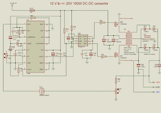
List Components DC To DC Converter +12 V To + / - 20V
R1, R2 = 10
R3, R4, R6, R7 = 1k
R5 = 22k
R8 = 4.7k
R9 = 100k
C1, C2 = 10000uF
C3, C6 = 47 u
C4 = 10U
C5, C7, C14 = 100n
C8, C9 = 4700u
C12 = 1N
C13 = 2.2u
U1 = TL494
U2 = TPS2811P
Q1, Q2 = FDB045AN
D1-D4 = 1N5822
D5 = 1N4148
FU1 = 10A
L1 = 10U
L2 = ferrite BEAD
RV1 = 2.2k
RV2 = 24k
T1 = TRAN-3P3S
DC To DC converter circuit +12 V To + / - 20V is capable of supplying up to 100W and can power supplying currents up to 3A. In making DC To DC Converter +12 V To + / - 20V has to be careful and cautious because there are parts of DC To DC Converter +12 V To + / - 20V in the form of an AC circuit.
Subscribe to:
Posts (Atom)